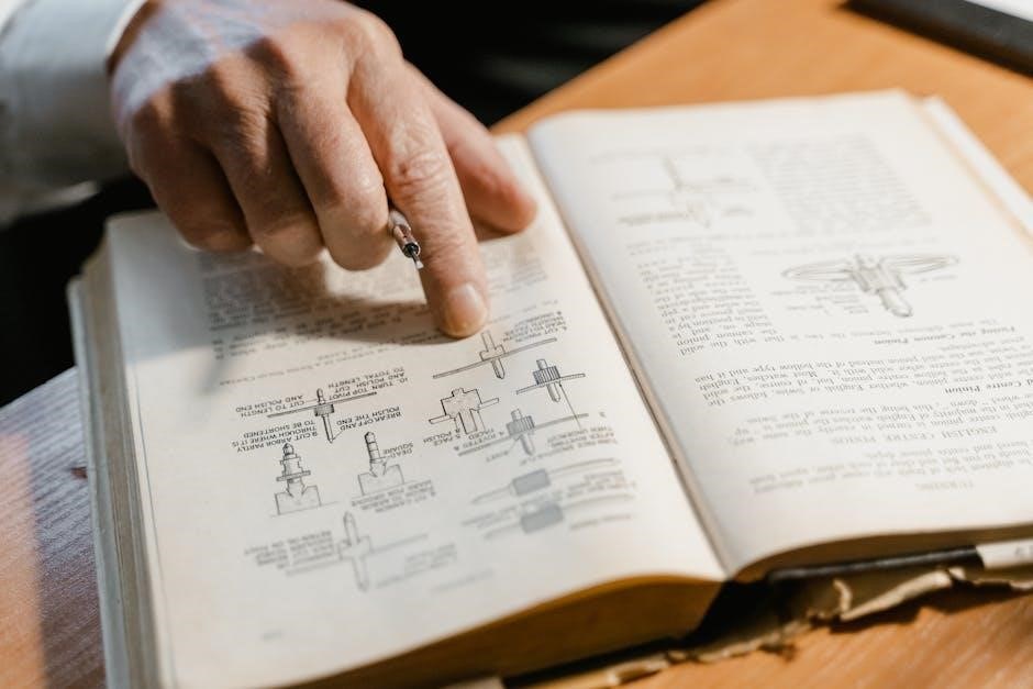
The John Deere 111 wiring diagram manual is a comprehensive guide for understanding and repairing the electrical system of this classic tractor model․ It provides detailed schematics and connections, essential for farmers, mechanics, and DIY enthusiasts to troubleshoot and maintain the tractor’s electrical components effectively․ This manual is a go-to resource for anyone aiming to restore or optimize their John Deere 111, ensuring smooth operation and longevity․
Overview of the Importance of Wiring Diagrams for Tractor Maintenance
Wiring diagrams are essential for maintaining and repairing the electrical systems of tractors like the John Deere 111․ They provide a clear visual representation of the tractor’s electrical circuits, making it easier to diagnose and fix issues․ These diagrams help identify faulty components, ensure proper connections, and guide safe repairs․ They are indispensable for farmers, mechanics, and DIY enthusiasts, preventing costly mistakes and ensuring the tractor operates efficiently and safely․
Understanding the John Deere 111 Wiring Diagram
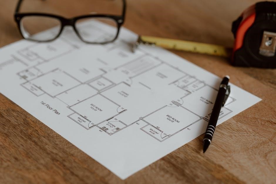
The John Deere 111 wiring diagram is a detailed blueprint that illustrates the electrical circuits and connections within the tractor․ It helps users identify components, trace circuits, and diagnose issues efficiently․ By understanding the diagram, one can pinpoint faults, ensure proper wire connections, and perform repairs confidently․ It’s essential for anyone working on the tractor’s electrical system․
How to Read and Interpret the Wiring Diagram
Reading the John Deere 111 wiring diagram involves identifying symbols, wire colors, and connections․ Start by locating the power source, typically marked by a battery or alternator symbol․ Trace circuits to understand the flow of current․ Use the legend to decode symbols and colors, ensuring accurate repairs․ Verify terminal labels and connections to avoid miswiring․ Always cross-reference with the manual to confirm component locations and functions․
- Identify key components like switches, solenoids, and fuses․
- Follow the flow of current from the power source․
- Refer to the diagram’s legend for symbol meanings․
Key Components and Their Functions in the Electrical System
The John Deere 111 electrical system includes essential components like the battery, starter solenoid, ignition switch, and PTO switch․ The alternator powers the system while the tractor is running, and fuses protect circuits from overloads․ Diodes regulate voltage, ensuring proper charging and preventing electrical damage․ Understanding these components and their roles is crucial for effective troubleshooting and maintenance of the tractor’s electrical system․
- Battery: Powers the starter and ignition system․
- Starter Solenoid: Activates the starter motor․
- Ignition Switch: Controls engine start-up and accessory power․
Sources for the John Deere 111 Wiring Diagram Manual
The manual can be sourced from official John Deere service publications, online forums like My Tractor Forum, or retailers like Jensales, offering detailed wiring schematics and repair guides․
Official John Deere Service Manuals and Publications
Official John Deere service manuals and publications provide authentic, detailed wiring diagrams and repair instructions for the John Deere 111 model․ These manuals are available through authorized dealers or the John Deere Technical Information Bookstore․ They include comprehensive schematics, troubleshooting guides, and step-by-step repair procedures, ensuring accuracy and reliability for maintenance and electrical system repairs․ Consulting these official resources is crucial for precise and safe tractor maintenance․
Online Communities and Forums for Wiring Diagram Availability
Online forums like MyTractorForum and Green Tractor Talk offer valuable resources for John Deere 111 wiring diagrams․ Users often share diagrams, troubleshooting tips, and repair experiences, providing practical solutions for common electrical issues․ These communities are indispensable for tractor enthusiasts and mechanics, offering real-world insights and support․ While official manuals are essential, forums complement them with shared knowledge and hands-on advice․
Troubleshooting Common Electrical Issues Using the Wiring Diagram
The wiring diagram aids in diagnosing issues like faulty connections and ignition problems by visually mapping the tractor’s electrical system, guiding precise repairs and ensuring functionality․
Identifying Faults in the Wiring Harness
Use the wiring diagram to locate and inspect connections for signs of damage, such as burns, frays, or corrosion․ Trace circuits systematically to identify open or shorted wires․ Test continuity with a multimeter to confirm proper connections․ Consult the manual for specific fault codes or symptoms, and follow step-by-step diagnostics to pinpoint issues․ This methodical approach ensures accurate identification and repair of wiring harness faults in the John Deere 111․
Common Repairs and Modifications Based on the Diagram
Common repairs include replacing melted or frayed wires, fixing faulty diodes, and correcting improper connections․ Modifications, such as adding LED lights or USB ports, can enhance functionality․ The wiring diagram guides these changes, ensuring compatibility and safety․ Regularly updating the system based on the manual prevents electrical failures and keeps the tractor running efficiently, whether for original operation or custom upgrades․

Safety Precautions When Working with Electrical Systems

Always disconnect the battery before starting repairs to prevent shocks or short circuits․ Use insulated tools and ensure proper grounding to avoid electrical hazards․ Follow the manual’s guidelines strictly to maintain safety while working on the tractor’s electrical components․
Essential Safety Practices for Tractor Electrical Repairs
Always disconnect the battery before starting any electrical repairs to prevent accidental power surges or shocks․ Use insulated tools to avoid direct contact with live circuits․ Ensure proper grounding of the tractor to eliminate static electricity risks․ Never work on electrical systems in wet conditions or near open flames․ Wear protective gear, including gloves and safety glasses, to safeguard against electrical arcs or flying debris․ Follow the John Deere 111 wiring diagram manual’s safety guidelines meticulously to avoid injuries or damage to components․
Specific Warnings for the John Deere 111 Model
The John Deere 111 model has specific warnings related to its electrical system․ Avoid overloading the single-wire alternator, as it may cause permanent damage․ Ensure the ignition switch is correctly wired to prevent system malfunctions or fire hazards․ Be cautious with older models, as they may lack polarized circuits, leading to unpredictable electrical behavior․ Never install modern high-power accessories, as they can overload the tractor’s original electrical system․ Always refer to the wiring diagram for accurate connections to maintain safety and functionality․

Tools and Materials Needed for Wiring Repairs
Essential tools for wiring repairs include a multimeter, wire strippers, crimpers, and a soldering iron․ Materials like heat-resistant tubing, marine-grade wire, and weatherproof connectors are recommended․ Ensure all components meet the tractor’s specifications to prevent damage․ Always consult the wiring diagram to identify the correct tools and materials for your specific repair․ Proper preparation ensures safety and durability in the electrical system of your John Deere 111․
Essential Tools for Diagram-Based Repairs
For diagram-based repairs, essential tools include a multimeter, wire strippers, crimpers, and a soldering iron․ A wiring harness repair kit, complete with heat-resistant tubing and connectors, is also crucial․ Additionally, marine-grade wire, circuit testers, and a fuse puller are recommended․ Always use tools that match the diagram’s specifications to ensure accurate and safe repairs․ Consulting the wiring diagram will help identify the exact tools needed for your specific electrical system task․
Recommended Materials for Rewiring or Repairing the Harness
For rewiring or repairing the harness, use marine-grade wire for durability and heat resistance․ Heat-resistant tubing protects wires from heat damage․ High-quality, weatherproof connectors ensure reliable connections and prevent corrosion․ Adhesives or sealants may be needed for watertight protection․ Circuit breakers and fuses are essential for system protection․ Always refer to the wiring diagram to ensure the correct materials are selected for your tractor’s specific electrical needs․
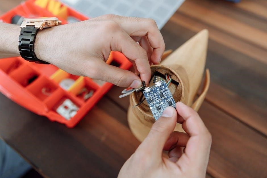
Identifying Components and Terminals in the Wiring Diagram
The wiring diagram uses symbols and labels to represent components like the ignition, alternator, and solenoid․ Wire colors indicate specific functions, while terminal labels clarify connections for accurate identification and troubleshooting․
Locating Key Electrical Components on the Tractor
The battery and starter solenoid are typically located under the hood or near the engine․ The ignition switch is usually mounted on the dashboard, while the alternator is positioned near the engine block․ Key components like the PTO switch and safety sensors are often found on the dashboard or attached to the chassis․ Refer to the wiring diagram to pinpoint exact locations and connections for each part․
Understanding Terminal Labels and Connections
Terminal labels in the John Deere 111 wiring diagram indicate connection points for wires, crucial for identifying where each component links․ Colors and symbols denote specific functions, such as power supply or ground wires․ Accurately interpreting these labels ensures correct connections, preventing electrical issues․ Always cross-reference the diagram with the tractor’s physical components to verify connections and facilitate safe, effective repairs and modifications․

DIY vs․ Professional Repair: When to Seek Expert Help
Minor electrical issues can often be resolved with DIY repairs using the wiring diagram․ However, complex problems or safety concerns require professional expertise to ensure proper functioning and safety․
Pros and Cons of DIY Electrical Repairs
DIY electrical repairs can save costs and empower tractor owners with hands-on knowledge․ However, improper fixes may lead to safety hazards or further damage․ Ensure you follow the wiring diagram accurately and use proper tools․ If unsure, consulting a professional is advisable to avoid risks and ensure reliability․
Scenarios That Require Professional Assistance
Complex electrical issues, such as melted wiring harnesses or incorrect terminal connections, often require professional expertise․ If the wiring diagram is unclear or the problem extends beyond basic troubleshooting, seeking help from a certified technician is crucial․ Professionals can safely address advanced repairs, ensuring reliability and preventing further damage or safety risks․
Best Practices for Maintaining and Updating the Wiring System
Regularly inspect wires and connections for wear or damage, update outdated components, and follow the wiring diagram for accurate repairs․ Consult the manual for specific guidelines․
Regular Maintenance Tips to Prevent Electrical Issues
Inspect wiring for frayed cables, corroded terminals, and damaged insulation․ Clean connections to prevent corrosion and ensure proper conductivity․ Check for loose wires and tighten connections; Replace any worn-out components promptly․ Use the wiring diagram to trace circuits and identify potential issues early․ Regularly test the battery and charging system to avoid electrical failures․ Keep the tractor stored in a dry environment to protect against moisture damage․
Documenting Custom Modifications for Future Reference
Keep detailed records of any custom wiring modifications using the John Deere 111 wiring diagram as a reference․ Note changes in wire connections, added components, and their purposes․ Store these records alongside the original manual for easy access․ This documentation helps prevent confusion during future repairs or upgrades and ensures consistency if modifications are repeated or shared with others, including professional mechanics․
