
Plan, elevation, and section drawings are fundamental in architecture and construction, providing detailed visual representations of buildings from horizontal, vertical, and cross-sectional perspectives to aid design and execution.

Understanding the Basics
Plan, elevation, and section drawings are essential tools in architecture and construction, offering distinct perspectives of a building. Plan drawings provide a horizontal view, slicing through the structure to reveal layouts and spatial relationships. Elevation drawings present vertical views, capturing the façade and exterior details. Section drawings expose the building’s interior by cutting through vertically or horizontally, revealing structural elements. These drawings use standardized lines, scales, and symbols to ensure clarity. By combining these views, architects and engineers can communicate design intent effectively, ensuring accurate construction and compliance with regulations. Understanding these fundamentals is crucial for interpreting and creating architectural documentation.
Plan Drawings
Plan drawings are a type of section drawn horizontally, revealing building layouts and spatial relationships. They are crucial for design and documentation, providing a clear overview of spaces.
Types of Plan Drawings
Plan drawings encompass various types, each serving specific purposes in architecture and construction. Floor plans illustrate the layout of individual floors, detailing rooms, doors, and windows. Site plans provide a broader view, showing the building’s placement on the property and its relationship with the surroundings. Roof plans focus on the roof’s design, including its shape, materials, and structural elements. Additionally, wall sections and cross-sections offer detailed views of specific building components, revealing their internal structures. These drawings are essential for clear communication among architects, engineers, and contractors, ensuring accuracy and consistency in project execution.
Floor Plans and Site Plans

Floor plans and site plans are essential tools in architectural design and construction. Floor plans provide a detailed, two-dimensional representation of each building level, showcasing room layouts, door placements, and window positions. These plans are crucial for understanding the internal spatial organization. Site plans, on the other hand, offer a broader perspective, illustrating the building’s position on the property, including landscaping, driveways, and surrounding structures. Together, they ensure that both the interior and exterior aspects of a project are well-coordinated and executed. Both types of plans are indispensable for architects, contractors, and clients to visualize and manage the project effectively.
Roof Plans and Wall Sections
Roof plans provide a detailed overview of a building’s roof layout, including slopes, ridges, valleys, and drainage systems. They are essential for understanding the roof’s structure and ensuring proper water runoff. Roof sections offer a cross-sectional view of the roof, revealing the layers of materials and structural elements like beams and insulation. Wall sections, similarly, provide a detailed look at the construction of walls, showcasing materials, thicknesses, and any embedded features such as electrical outlets or insulation. These drawings are critical for both design and construction, allowing architects and builders to visualize and execute the building’s structural integrity effectively.
Elevation Drawings
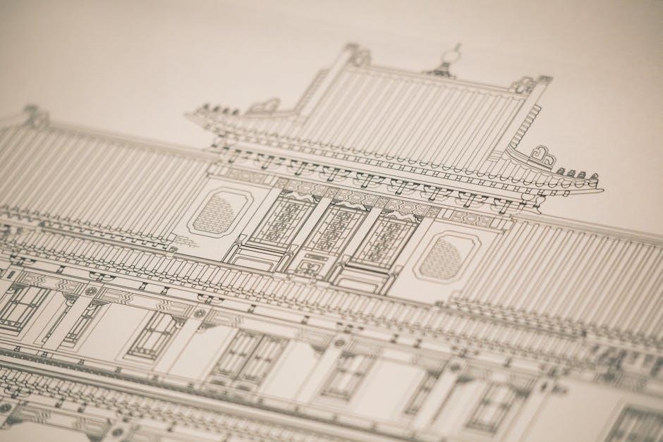
Elevation drawings are detailed representations of a building’s exterior faces, capturing front, side, and rear views. They provide precise measurements and design elements for construction and visualization purposes.
Front, Side, and Rear Elevations
Front, side, and rear elevations are detailed orthographic views of a building’s exterior faces, captured from specific directions. These drawings provide a 2D representation of the building’s appearance, including architectural features, windows, doors, and material textures. Front elevation focuses on the main façade, often highlighting the entrance and primary design elements. Side and rear elevations offer complementary views, ensuring a comprehensive understanding of the structure’s proportions and aesthetics. These drawings are essential for construction planning, allowing architects and builders to visualize and execute the design accurately while adhering to regulatory standards and maintaining design consistency.
3D Perspectives and Exterior Elevations
3D perspectives and exterior elevations offer a comprehensive visual representation of a building’s form and design. Exterior elevations provide detailed 2D views of each façade, capturing architectural elements such as windows, doors, and textures. These are often complemented by 3D perspectives, which present a three-dimensional view of the structure, enhancing the understanding of its spatial relationships and aesthetic appeal. Together, they serve as crucial tools for architects, allowing them to communicate their vision effectively to clients and stakeholders. These drawings are essential for project development, ensuring that the final construction aligns with the intended design and regulatory requirements. They also facilitate collaboration among various project teams.
Section Drawings
Section drawings are detailed vertical cuts through buildings, illustrating internal structures and components. They reveal architectural elements, materials, and spatial relationships, aiding in design and construction planning.
Wall Sections and Roof Sections
Wall sections provide detailed views of a building’s vertical elements, showcasing materials, layers, and structural components. They often include dimensions, construction methods, and specific materials used, such as insulation or drywall. Roof sections similarly offer a cross-sectional view of roofing systems, highlighting slopes, supports, and coverings. Both types of sections are essential for understanding a building’s structural integrity and aesthetic appeal. They are typically drawn to scale, allowing architects and contractors to visualize and execute designs accurately. These sections are critical for ensuring compliance with building codes and for resolving potential construction challenges early in the planning process.
cross Sections and Detailed Views

Cross Sections and Detailed Views

Cross sections provide in-depth views of specific building elements, revealing internal structures and material layers. They are essential for understanding complex details, such as staircases or roof intersections. Detailed views further magnify specific components, like door frames or beam connections, ensuring precise construction. Both are drawn to scale, offering clarity on dimensions and assembly. These drawings are vital for resolving design complexities and ensuring structural integrity. They also help contractors visualize how elements interact, aiding in accurate execution. Cross sections and detailed views are indispensable tools in architectural and construction documentation, bridging the gap between design intent and physical realization.

Creating Plan, Elevation, and Section Drawings
Creating plan, elevation, and section drawings involves precise measurements and detailed documentation. These drawings are developed through stages of preparation, site analysis, and design refinement to ensure accuracy and compliance.
Tools and Software
Creating plan, elevation, and section drawings requires specialized tools and software. Popular applications include AutoCAD, Revit, SketchUp, and ArchiCAD, which enable precise 2D and 3D modeling. These tools offer features like layer management, scaling, and cross-section views, ensuring accuracy. Additionally, SolidWorks and Rhino are used for complex geometries. Online platforms like Floorplanner simplify floor plan creation, while Blender and 3ds Max aid in 3D visualization. Proper software ensures drawings meet professional standards and are easily shareable with stakeholders. Regular updates and training are essential to master these tools and streamline the design process.
Best Practices and Standards
Adhering to best practices and standards is crucial for creating clear and accurate plan, elevation, and section drawings. Consistency in scales, symbols, and notations ensures uniformity across all documents. Proper labeling and cross-referencing between views are essential to avoid ambiguity. Industry standards, such as those set by ISO or local building codes, must be followed to ensure compliance; Use of layer management in software like AutoCAD or Revit helps organize complex designs. Regularly updating drawings and incorporating feedback ensures accuracy. Additionally, maintaining a logical naming convention for files and layers enhances collaboration. These practices guarantee that drawings are professional, precise, and easily interpretable by all stakeholders.
Importance in Architecture and Construction
Plan, elevation, and section drawings are essential for clear communication among architects, engineers, and contractors, ensuring projects are executed accurately and comply with regulations.
Role in Project Development
Plan, elevation, and section drawings play a pivotal role in project development by providing clear visual representations of a building’s design. These drawings enable architects and engineers to communicate their vision effectively to clients and contractors, ensuring alignment throughout the project lifecycle. They facilitate the identification of potential design flaws early in the process, reducing costly revisions later. By detailing spatial relationships, materials, and structural elements, these drawings guide construction teams in executing the design accurately. Additionally, they serve as legal documents for obtaining approvals and ensuring compliance with building codes, making them indispensable tools for successful project planning and execution.
Compliance with Regulations
Plan, elevation, and section drawings are essential for ensuring compliance with building codes and regulations. These drawings provide detailed visual representations of a building’s design, enabling authorities to verify that all elements meet legal and safety standards. By clearly depicting structural components, spatial layouts, and material specifications, they help ensure adherence to local, state, and national regulations. Additionally, these drawings serve as legal documents for obtaining construction permits and approvals. Their precision and accuracy are critical for avoiding violations and ensuring that projects align with regulatory requirements, thereby safeguarding public safety and maintaining architectural integrity throughout the construction process.