Welcome to the DITRA-HEAT Thermostat Installation Manual, your comprehensive guide to installing and configuring the DITRA-HEAT-E-RS1 smart thermostat and related components․ This manual ensures safe and optimal setup of your floor heating system, covering compatibility, wiring, and advanced features for smart home integration․ Follow the detailed instructions carefully to achieve precise temperature control and energy efficiency․
System Components and Compatibility
The DITRA-HEAT system includes the E-RS1 smart thermostat, E-RRS power module, and compatible heating cables․ Ensure components are rated for your voltage (120V/240V) and wiring setup for seamless operation․
DITRA-HEAT-E-RS1 Smart Thermostat Overview
The DITRA-HEAT-E-RS1 is a sleek, Wi-Fi-enabled smart thermostat designed for the DITRA-HEAT floor warming system․ It features a mirror-finish display and integrates with popular smart home systems like Apple Home, Google Home, and Alexa for voice control․ This thermostat offers programmable scheduling and remote access via the Schluter-HEAT-CONTROL app, ensuring convenient temperature management․ Its compatibility with 120V and 240V heating cables makes it versatile for various installation needs, while maintaining energy efficiency and precise temperature control․ Proper installation requires a GFCI-protected circuit and adherence to wiring guidelines for optimal performance․
DITRA-HEAT-E-RRS Power Module Requirements
The DITRA-HEAT-E-RRS power module is essential for systems requiring more than 15 amps․ It is specifically designed to work with the DITRA-HEAT-E-RS1 smart thermostat, ensuring reliable power distribution to heating cables․ The module requires a 20 AWG, 300-volt rated wire (CL2/CL3 or CM for the USA, CMG/FT4 for Canada) for connections․ It supports multiple power modules in a daisy-chain configuration, allowing for scalable installations․ Proper installation must include a GFCI-protected circuit to meet safety standards and ensure optimal performance․ Always follow the wiring diagram provided in the manual for correct connections․
Heating Cable Compatibility and Specifications
The DITRA-HEAT system uses compatible heating cables designed for underfloor and wall heating applications․ Available in 120-volt and 240-volt configurations, these cables ensure flexibility for various installation needs․ Proper installation requires placing cables at least 3 inches from the edge of the KERDI-BOARD and avoiding direct contact with wood studs․ The cables must be installed with a floor temperature sensor to monitor and control heat distribution accurately․ Always use cables rated for your specific voltage requirements and follow the manufacturer’s guidelines to ensure safe and efficient operation․
Temperature Sensor Installation Guidelines
Install the floor temperature sensor supplied with the DITRA-HEAT-E-HK heating cable(s) to ensure accurate temperature monitoring․ Place the sensor between two heating cables, securing it with tape or a clip․ If using a different sensor, ensure it is 300-volt rated and meets all system requirements․ Proper placement prevents overheating and ensures efficient heat distribution․ Always turn off power before installing or adjusting the sensor․ Follow the manufacturer’s instructions for precise placement and connection to the thermostat for optimal system performance and safety․

Installation Prerequisites
Ensure compatibility with voltage and wiring requirements․ Verify power supply meets system demands, and check circuit ratings to support the thermostat and heating components effectively before starting installation․
Compatibility Check for Voltage and Wiring
Verify that your system operates within the required voltage range (120V or 240V) and ensure wiring matches the specified 20 AWG, 300-volt rated cable (CL2/CL3 or CM for the USA, CMG/FT4 for Canada)․ Check circuit ratings to handle the maximum current draw, especially when exceeding 15 amps, which requires the DITRA-HEAT-E-RRS power module․ Ensure all connections comply with local electrical codes and system specifications for safe and efficient operation․
Ensuring Proper Power Supply and Circuit Requirements
Ensure the power supply matches the system’s voltage requirements (120V or 240V) and verify that a dedicated circuit is installed for the floor heating system․ Use a DITRA-HEAT-E-RRS power module for loads exceeding 15 amps․ Always follow local electrical codes and ensure the circuit breaker or fuse box can handle the maximum current draw․ Proper installation prevents overheating and ensures reliable operation․ Consult the installation manual for specific power module configurations and system compatibility to maintain safety and efficiency․
Step-by-Step Installation Process
Follow the structured guide to install the DITRA-HEAT system, starting with site preparation, thermostat mounting, and wire connections․ Proceed to integrate the temperature sensor and connect power modules, ensuring all components are securely linked for optimal performance․
Preparing the Site for Thermostat Installation
Before installing the DITRA-HEAT thermostat, ensure the installation site is clear of debris and obstructions․ Verify that the area is accessible and free from moisture․ Check the electrical system to confirm compatibility with the thermostat’s voltage requirements․ Ensure all necessary tools and materials, such as wire strippers and connectors, are available․ Review the wiring diagram and system specifications to confirm proper connections․ This preparation ensures a smooth and safe installation process for the DITRA-HEAT-E-RS1 smart thermostat and related components․
Mounting the Thermostat and Connecting Wires
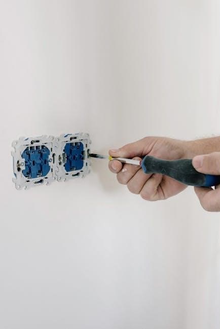
Mount the DITRA-HEAT-E-RS1 thermostat on a flat, dry wall surface, ensuring it is level and secure․ Turn off the power supply before starting; Connect the wires according to the wiring diagram, using 20 AWG signal or communication wires rated for 300 volts․ Attach AUX 1 and 2 from the thermostat to AUX IN on the power module, and AUX OUT to AUX IN for additional modules․ Strip wires to the recommended length and secure connections with approved wire nuts or connectors․ Double-check all connections for accuracy and compatibility with the DITRA-HEAT-E-RRS power module before restoring power․
Integrating the Temperature Sensor
Mount the temperature sensor near the heating cables, ensuring it is not in direct contact with them․ Connect the sensor to the thermostat using 20 AWG wires rated for 300 volts․ Follow the wiring diagram to attach the sensor leads to the designated terminals․ Secure the sensor to prevent movement and ensure accurate readings․ Verify compatibility with the thermostat and power requirements․ Calibrate the sensor if necessary, and test the system to confirm proper function․ Always turn off power before handling wires or the sensor to ensure safety and prevent damage․
Connecting Power Modules and Heating Cables
Connect the DITRA-HEAT-E-RRS power module to the thermostat using 20 AWG, 300-volt rated wires (CL2/CL3 or CM for USA, CMG/FT4 for Canada)․ Attach AUX 1 and 2 from the thermostat to AUX IN on the power module․ For multiple power modules, connect AUX OUT to AUX IN․ Ensure the heating cables are compatible and securely connected to the power module․ Use the Schluter-DITRA-HEAT-E-RRS for systems requiring over 15 amps․ Verify all connections are secure and meet safety standards before powering up the system․

Smart Home Integration and App Connectivity
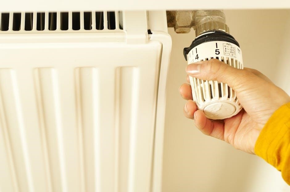
Seamlessly integrate your DITRA-HEAT thermostat with smart home systems like Apple Home, Google Home, and Alexa for voice control and enhanced convenience․ Use the Schluter-HEAT-CONTROL app to configure settings, monitor temperatures, and optimize energy usage remotely․
Linking the Thermostat to Smart Home Systems
Link your DITRA-HEAT-E-RS1 thermostat to popular smart home platforms like Apple Home, Google Home, or Alexa for seamless voice control․ Start by enabling Wi-Fi on the thermostat and downloading the Schluter-HEAT-CONTROL app․ Follow in-app instructions to connect your thermostat to your smart home system․ Once linked, you can adjust temperatures, create schedules, and monitor energy usage remotely․ Ensure your thermostat is properly configured in the app for full integration․ This setup enhances convenience and optimizes your floor warming system’s performance․
Configuring the Schluter-HEAT-CONTROL App
Download and install the Schluter-HEAT-CONTROL app from the App Store or Google Play․ Create a user account or log in if you already have one․ Open the app and navigate to the “Add Device” section․ Select your DITRA-HEAT-E-RS1 thermostat from the list of available devices․ Follow the in-app instructions to connect your thermostat to your Wi-Fi network․ Once connected, customize settings such as temperature preferences, schedules, and energy usage monitoring․ Ensure your thermostat is properly paired to the app for seamless control and optimal performance․
Safety Considerations and Best Practices
Always adhere to electrical safety standards and ensure GFCI protection is installed․ Handle live wires with caution, and disconnect power before servicing․ Follow all installation guidelines to prevent hazards․
Electrical Safety Precautions During Installation

Always adhere to electrical safety standards to prevent hazards․ Ensure GFCI protection is installed and operational before starting the installation․ Disconnect power supplies before servicing or connecting wires; Use 300-volt rated wires for all connections to avoid electrical faults․ Avoid overloading circuits, and never bypass safety devices․ Properly ground all components to prevent shocks․ If unsure, consult a qualified electrician․ Follow the manual’s guidelines strictly to ensure a safe and reliable installation․
Ground Fault Circuit Interrupter (GFCI) Protection
A Ground Fault Circuit Interrupter (GFCI) is essential for safe operation of the DITRA-HEAT system․ Ensure the circuit is equipped with a dedicated 20-amp GFCI breaker to protect against ground faults and electrical shocks․ The GFCI must comply with local electrical codes and be compatible with the system’s voltage requirements (120V or 240V)․ Failure to install GFCI protection increases the risk of electrical hazards․ Always test the GFCI after installation to ensure proper functionality․ This critical safety measure is mandatory for all DITRA-HEAT installations․
Ensuring Proper Sensor Placement
Proper placement of the temperature sensor is crucial for accurate temperature control and system performance․ The sensor should be positioned between the heating cables and the subfloor, ensuring it is not in direct contact with the cables․ Use the supplied 300-volt rated sensor or an equivalent that meets specifications․ Secure the sensor with heat-resistant tape to prevent movement․ Avoid placing the sensor near the thermostat or power module to prevent interference․ Follow the manufacturer’s guidelines for spacing and installation to ensure reliable operation and safety․ Proper sensor placement guarantees precise temperature monitoring and optimal system efficiency․
Troubleshooting and Maintenance
Common issues include incorrect passwords and sensor malfunctions․ Regularly inspect wiring and sensors for damage․ Ensure GFCI protection is functioning properly for safety․ Routine maintenance ensures optimal performance and prevents system failures․
Common Issues and Solutions
Common issues with the DITRA-HEAT thermostat include incorrect passwords, sensor malfunctions, and wiring problems․ Ensure the power supply is stable and GFCI protection is functioning․ If the thermostat fails to connect to smart home systems, reset the device and reconnect․ For sensor issues, verify proper placement and ensure no physical obstructions․ Check wiring for damage or loose connections․ Regularly update the Schluter-HEAT-CONTROL app to avoid compatibility issues․ Refer to the user manual for detailed troubleshooting steps and solutions to maintain optimal system performance․
Regular Maintenance for Optimal Performance
Regular maintenance ensures the DITRA-HEAT system operates efficiently․ Check the temperature sensor for accuracy and proper placement․ Inspect wiring connections for damage or wear․ Ensure the thermostat and power modules are free from dust or obstructions․ Update the Schluter-HEAT-CONTROL app periodically to access new features and improvements․ Perform a system reset every 6 months to clear cached data․ Verify GFCI protection is functioning correctly and test ground fault circuit interrupters annually․ Maintain consistent power supply to avoid system malfunctions and ensure reliable floor heating performance․

Warranty and Technical Support
Schluter Systems offers a 3-year limited warranty for the DITRA-HEAT thermostat when installed according to manual guidelines․ Technical support and resources are available online for troubleshooting and assistance․
Understanding the Warranty Terms
The DITRA-HEAT thermostat and associated components are covered by a 3-year limited warranty from Schluter Systems․ This warranty applies to defects in materials and workmanship when the product is installed according to the installation manual․ Proper installation, as outlined in the guide, is essential for warranty validation․ For full details, including coverage limitations and disclaimers, refer to the official Schluter Systems website or contact their customer support team․ Warranty claims must be submitted with proof of purchase and installation compliance․
Accessing Technical Support and Resources
For assistance with your DITRA-HEAT thermostat, Schluter Systems provides comprehensive technical support and resources․ Visit their official website to access product manuals, installation guides, and troubleshooting tips․ The Schluter-HEAT-CONTROL app also offers in-app support features․ Additionally, contact their customer service team directly for personalized help․ Ensure you have your product serial number and installation details ready for efficient support․ Regularly check for software updates and maintenance tips to optimize your system’s performance and longevity․
